
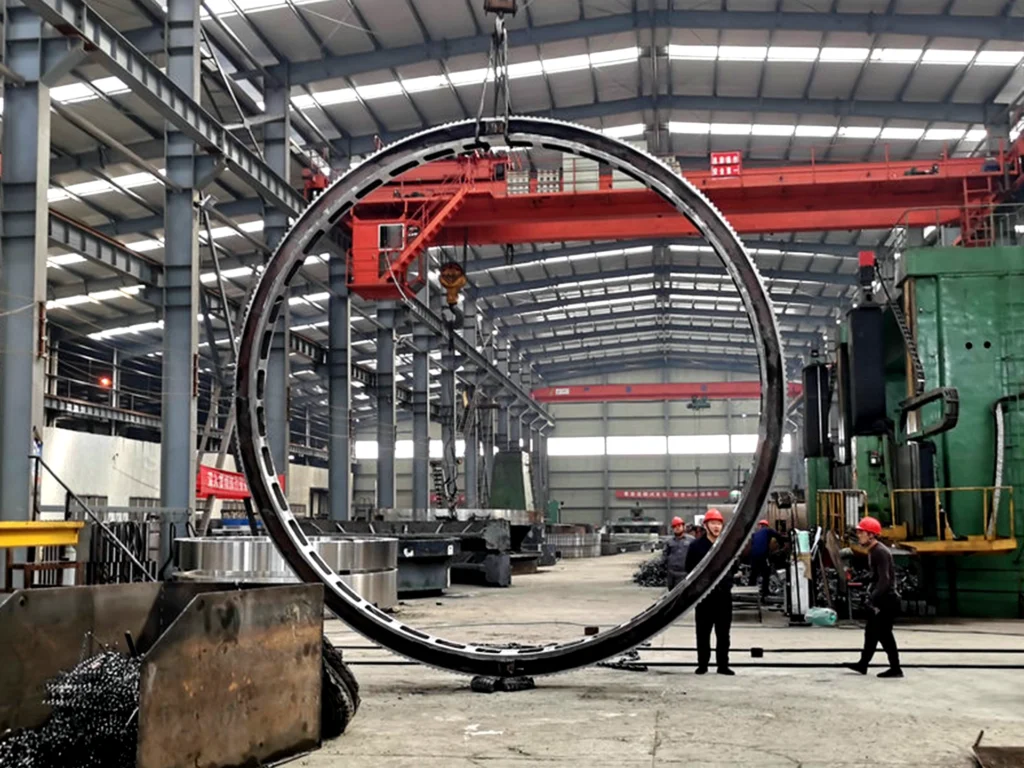
Heavy-Duty Girth Gear Manufacturing & Engineering Services
Technical Instructions for Operation and Installation of Rotary Kiln Girth Gear
▸ Stability of equipment operation
▸ Operating rate of the entire machine
Structural Configuration and Installation Location for Large Girth Gear
Split-body structure
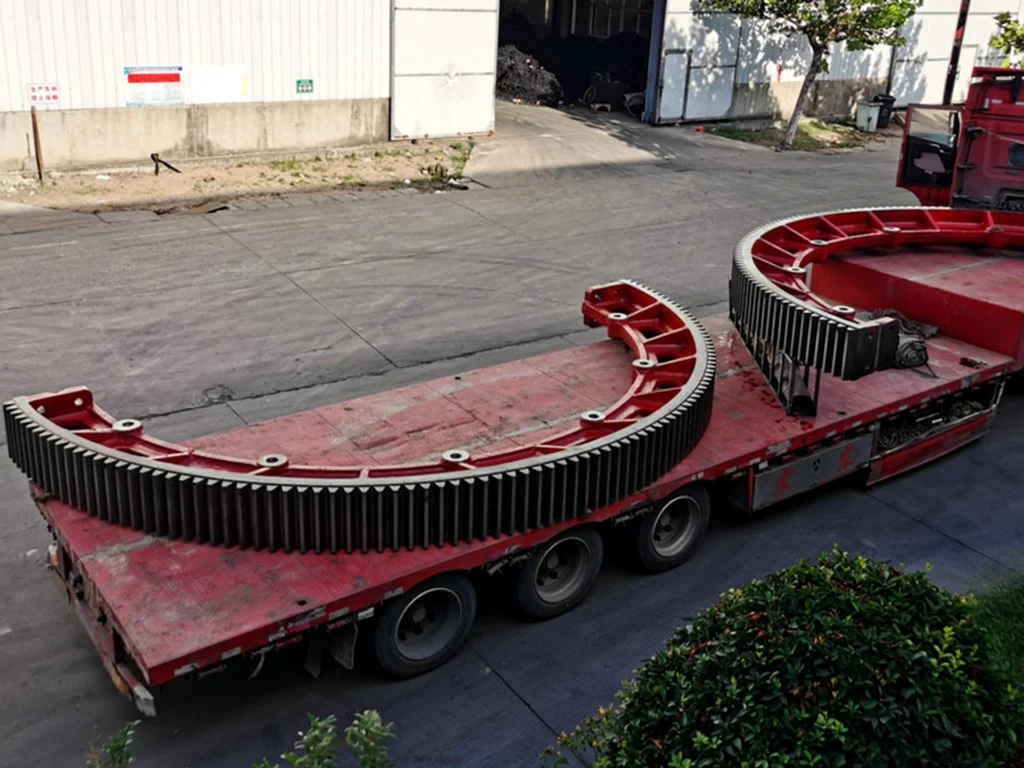
Due to the large outer diameter of the large gear, it is typically designed as a split structure—consisting of two halves or several segments—and assembled into a single unit using high-strength bolts to facilitate transport and lifting
Installation location
The large gear is generally positioned near the middle of the kiln shell. This location offers the following advantages:
▸ Ensures uniform load distribution on the kiln shell, preventing localized stress concentration
▸ Positions the gear away from the hot end (kiln head), minimizing the impact of high temperatures on gear material
▸ Keeps the gear away from the dusty zone at the kiln discharge end, helping to extend its service life
▸ Facilitates routine inspection and maintenance operations
The installation centerline of the large gear must strictly coincide with the centerline of the cylinder to ensure uniform distribution of the transmission load and prevent wear caused by uneven loading.
Connection method between the large gear and the shell
| Comparison Item | Tangential Connection (Tangential Spring Plate Connection) | Axial Connection (Longitudinal Spring Plate Connection) |
|---|---|---|
| Structural Principle | The girth gear is fixed in the tangential direction of the kiln shell via spring plates. The spring plates are typically made of 20–30mm thick steel plates, with a width consistent with the pitch circle of the gear; one end is welded to the base plate along the tangential direction of the kiln shell, and the other end is connected to the girth gear flange by bolts. | The girth gear is fixed on elastic steel plates parallel to the axis of the kiln shell, and the steel plates are arranged along the circumferential direction of the kiln shell. |
| Adjustment Method | Shims can be added at the joint surface to fine-tune the concentricity between the center of the girth gear and the center of the kiln shell. | The means of adjustment are limited. |
| Advantages | It possesses excellent elasticity, which can effectively cushion the bending deformation of the kiln shell and the shock loads during startup and shutdown, protecting the smooth meshing of the large and small gears. | Simple manufacturing process and quick, convenient installation. |
| Disadvantages | Installation and alignment are highly difficult, requiring high technical skills from installation personnel; the manufacturing and processing of the girth gear body itself is complex. | Poor elasticity when transmitting torque, weak shock resistance, and limited cushioning effect. |
| Application Status | Widely adopted, it is the mainstream solution for rotary kiln girth gear connections. | Seldom adopted, generally used only for small-scale or non-critical equipment. |
Custom Girth Gear Manufacturer
As a leading custom girth gear manufacturer, we engineer high-precision, wear-resistant transmission solutions tailored to your machinery’s exact specifications. Whether you need an emergency upgrade or routine maintenance components, we have you covered.
- Buy rotary kiln girth gear solutions built to withstand extreme thermal and operational stress.
- Source premium girth gear replacement parts including pinions, springs, and hardware.
- Partner with an industry-approved girth gear supplier delivering global logistical support.
Recommendations for Use and Maintenance
| 5.1 Installation Phase |
|
| 5.2 Operation & Maintenance Phase |
|
| 5.3 Precautions & Warnings |
⚠️ WARNING:
In the tangential connection structure, the shim adjustment amount should be moderate. Avoid excessive shimming, which can lead to stress concentration in the spring plates.
⚠️ WARNING:
After the installation of the girth gear is complete, the runout values must be measured under both cold and hot (operational) states to ensure that accuracy requirements are met across all operating conditions.
|
Girth Gear Technical & Maintenance FAQ
- Lower Component Weight: Individual segments are significantly lighter, reducing structural stress during handling.
- Easier Transportation: Easier to pack and ship worldwide, dropping heavy freight or specialized transit costs.
- Simplified Maintenance: They allow for local or partial sector replacement in the event of localized tooth damage, bypassing the need to remove the entire ring.
- Installation Phase: Radial and axial runouts must be strictly controlled within the equipment’s specified tolerances to eliminate uneven gear tooth loading. Utilize adjusting shims to precisely align the centerlines of the girth gear and the shell/drum barrel.
- Running Maintenance Phase: Establish a regular inspection schedule to monitor spring plate weld seams and bolt tightness against vibration. Ensure an open-gear lubrication system consistently applies recommended grease/oil charts, and continuously track wear patterns to resolve any abnormal wear immediately.
- Avoid over-shimming or excessive adjustment in tangential spring plate connection structures, as over-tightening results in severe local stress concentration.
- Once installation is complete, runout values must be thoroughly tested and recorded under both cold (ambient) and hot (operational) states to guarantee high precision across all thermal working conditions, preventing cyclic thermal stresses.