
C Series
Marine Hydraulic Cylinders
The C-series marine hydraulic cylinders—available in both double-acting piston and single-acting plunger types—are suitable for a wide range of ship deck machinery and offshore engineering equipment, featuring a compact design, high reliability, and excellent corrosion resistance.
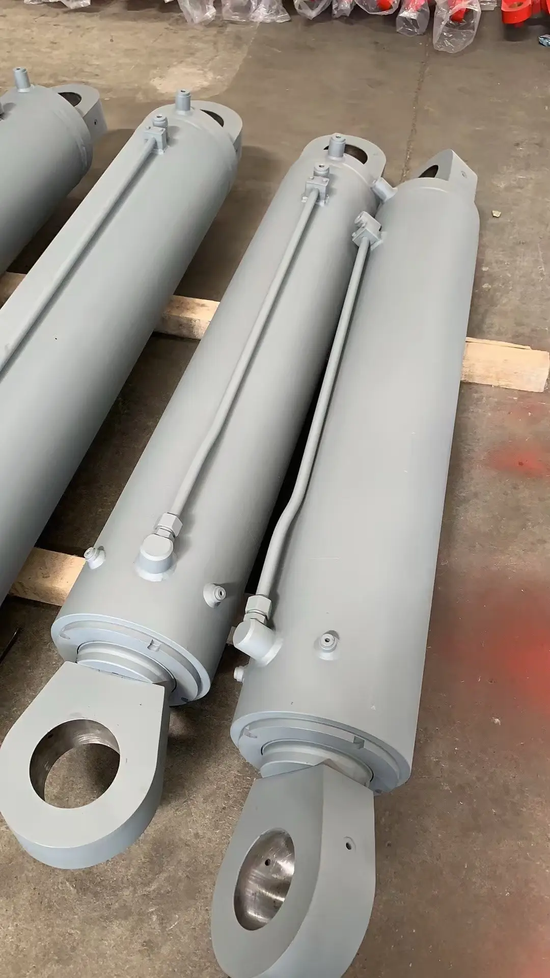
C-Series Marine Hydraulic Cylinders
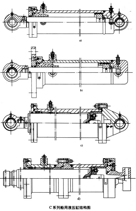
Structural Diagram of C-Series Marine Hydraulic Cylinder
Explanation of Model Coding for C-Series Marine Hydraulic Cylinders
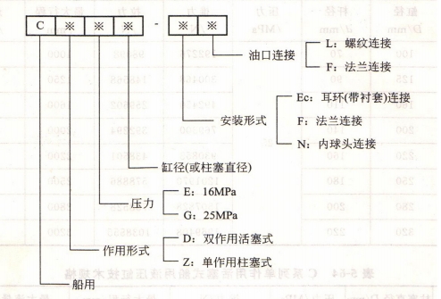
The C-series marine hydraulic cylinder is a hydraulic actuator specifically designed for marine and offshore environments; it primarily comprises two main series: **double-acting piston-type (CDE/CDG)** and **single-acting plunger-type (CZE/CZG)**.
- Model example: CDE100—"C" stands for marine application, "D" for double-acting, "E" for a 16 MPa pressure rating, and "100" for a cylinder bore of 100 mm.
It features a compact design and utilizes seawater-resistant materials and surface treatment processes, making it suitable for the drive and control of various deck machinery, such as ship rudders, hatch covers, cranes, and anchor winches.
CDE Series Technical Specifications (Pressure Rating: 16 MPa)
| Model | Bore D (mm) | Rod Diameter d (mm) | Pressure (MPa) | Push Force (N) | Pull Force (N) | Max. Stroke (mm) | Max. Flow Rate (L/min) |
|---|---|---|---|---|---|---|---|
| CDE40 | 40 | 22 | 16 | 19698 | 13720 | 400 | 9 |
| CDE50 | 50 | 28 | 30772 | 21070 | 500 | 14 | |
| CDE63 | 63 | 35 | 48804 | 33810 | 630 | 22 | |
| CDE80 | 80 | 45 | 78792 | 53990 | 800 | 35 | |
| CDE100 | 100 | 55 | 123088 | 85848 | 1000 | 55 | |
| CDE125 | 125 | 70 | 192374 | 132104 | 1250 | 86 | |
| CDE160 | 160 | 90 | 315266 | 215600 | 1600 | 140 | |
| CDE200 | 200 | 110 | 492548 | 343686 | 2000 | 220 | |
| CDE220 | 220 | 125 | 595742 | 493368 | 2200 | 260 | |
| CDE250 | 250 | 140 | 769594 | 528318 | 2500 | 340 | |
| CDE280 | 280 | 160 | 965006 | 649838 | 2800 | 420 | |
| CDE320 | 320 | 180 | 1261260 | 862400 | 3200 | 546 | |
| CDE360 | 360 | 200 | 1595146 | 1102784 | 3600 | 690 | |
| CDE400 | 400 | 220 | 1969048 | 1373568 | 4000 | 850 |
CDG Series Technical Specifications (Pressure Rating: 25 MPa)
| Model | Bore D (mm) | Rod Diameter d (mm) | Pressure (MPa) | Push Force (N) | Pull Force (N) | Max. Stroke (mm) | Max. Flow Rate (L/min) |
|---|---|---|---|---|---|---|---|
| CDG100 | 100 | 70 | 25 | 192276 | 98098 | 1000 | 55 |
| CDG125 | 125 | 90 | 300468 | 148568 | 1250 | 86 | |
| CDG160 | 160 | 110 | 492450 | 259602 | 1600 | 140 | |
| CDG200 | 200 | 140 | 769300 | 392294 | 2000 | 220 | |
| CDG220 | 220 | 160 | 930853 | 438501 | 2200 | 258 | |
| CDG250 | 250 | 180 | 1201970 | 578886 | 2500 | 340 | |
| CDG280 | 280 | 200 | 1507828 | 738528 | 2800 | 418 | |
| CDG320 | 320 | 220 | 1969408 | 1038555 | 3200 | 546 |
Mounting Dimensions for CDE/CDG Series Double-Acting Piston-Type Marine Hydraulic Cylinders
CDE Series (Ec Type) Clevis-Mount Dimensions and Mounting Specifications
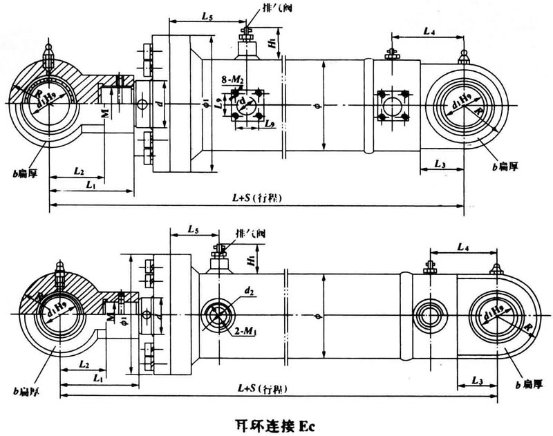
| Parameters | CDE40 | CDE50 | CDE63 | CDE80 | CDE100 | CDE125 | CDE160 | CDE200 | CDE220 | CDE250 | CDE280 | CDE320 | CDE360 | CDE400 |
|---|---|---|---|---|---|---|---|---|---|---|---|---|---|---|
| Cylinder bore D | 40 | 50 | 63 | 80 | 100 | 125 | 160 | 200 | 220 | 250 | 280 | 320 | 360 | 400 |
| Rod diameter d | 22 | 28 | 35 | 45 | 55 | 70 | 90 | 110 | 125 | 140 | 160 | 180 | 200 | 220 |
| d1 | 20 | 30 | 40 | 50 | 50 | 60 | 80 | 80 | 90 | 100 | 110 | 125 | 140 | 150 |
| Φ | 50 | 63 | 76 | 95 | 121 | 152 | 194 | 245 | 273 | 299 | 351 | 377 | 435 | 470 |
| Φ1 | 85 | 95 | 115 | 135 | 205 | 205 | 245 | 290 | 330 | 370 | 430 | 470 | 560 | 575 |
| Φ2 | 135 | 155 | 185 | 205 | 310 | 310 | 360 | 435 | - | - | - | - | - | - |
| Φ3 | 110 | 125 | 150 | 170 | 215 | 260 | 300 | 360 | - | - | - | - | - | - |
| Φ4 | 40 | 50 | 63 | 80 | 100 | 125 | 160 | 200 | - | - | - | - | - | - |
| Φ5 | 11 | 13 | 17 | 17 | 22 | 26 | 29 | 38 | - | - | - | - | - | - |
| n | 8 | 8 | 8 | 8 | 12 | 12 | 12 | 12 | - | - | - | - | - | - |
| L | 255 | 295 | 345 | 390 | 480 | 640 | 765 | 825 | 890 | 890 | 985 | 1085 | 1225 | 1340 |
| L1 | 70 | 87 | 94 | 119 | 165 | 240 | 233 | 248 | 263 | 273 | 301 | 333 | 346 | 340 |
| L2 | 25 | 30 | 35 | 37 | 38 | 52 | 58 | 61 | 70 | 79 | 85 | 90 | 95 | 95 |
| L3 | 33 | 43 | 43 | 53 | 70 | 70 | 80 | 100 | 140 | 172 | 185 | 205 | 230 | 250 |
| L4 | 49 | 64 | 66 | 78 | 95 | 115 | 143 | 143 | 159 | 172 | 189 | 205 | 235 | 250 |
| L5 | 45 | 50 | 60 | 65 | 86 | 95 | 110 | 110 | 115 | 124 | 135 | 145 | 160 | 190 |
| L6 | 225 | 254 | 305 | 337 | 422 | 575 | 680 | - | - | - | - | - | - | - |
| L7 | 19 | 20 | 25 | 25 | 37 | 41 | 50 | 58 | - | - | - | - | - | - |
| L8 | 69 | 85 | 92 | 117 | 163 | 197 | 232 | - | - | - | - | - | - | - |
| H | 14 | 17 | 20 | 23 | 28 | 32 | 40 | 46 | - | - | - | - | - | - |
| H1 | 25 | 25 | 25 | 25 | 65 | 65 | 65 | 65 | 65 | 65 | 65 | 65 | 65 | 65 |
| b | 25 | 35 | 35 | 45 | 60 | 70 | 90 | 100 | 110 | 110 | 120 | 135 | 165 | 200 |
| r | 25 | 35 | 35 | 45 | 60 | 70 | 90 | 100 | 110 | 110 | 120 | 135 | 165 | 200 |
| d2 | 8 | 10 | 15 | 15 | 20 | 25 | 32 | 40 | 40 | 50 | 50 | 50 | 65 | 65 |
| L9 | - | - | - | - | - | - | - | - | - | - | - | - | - | - |
| M | M18×1.5 | M22×1.5 | M27×2 | M32×2 | M42×2 | M52×2 | M68×2 | M85×2 | M90×3 | M100×3 | M115×3 | M130×3 | M145×3 | M160×3 |
| M1 | M18×1.5 | M22×1.5 | M27×2 | M27×2 | M33×2 | M33×2 | M42×2 | M48×2 | M48×2 | M16 | M16 | M16 | M16 | M16 |
| M2 | - | - | - | - | - | - | - | - | - | - | - | - | - | - |
Description of Key Parameters:
- Bore D: Hydraulic cylinder internal diameter (mm)
- Rod diameter d: Piston rod diameter (mm)
- Φ, Φ1, Φ2, Φ3, Φ4, Φ5: Diameter dimensions for mounting flanges, end caps, etc. (mm)
- n: Number of mounting bolt holes
- L, L1, L2, ... L9: Length dimensions of various cylinder components (mm)
- H, H1: Mounting height dimensions (mm)
- b, r: Dimensions such as mounting flange width and radius (mm)
- d2: Pin hole diameter (mm)
- M, M1, M2: Oil port thread specifications (metric fine thread)
- -: Indicates that this model does not have this dimension or parameter
CDE Series Type F (Front Flange Mount) Outline and Mounting Dimensions Table
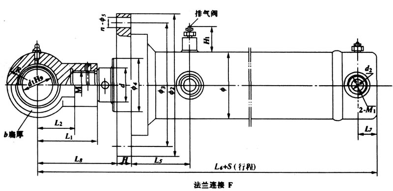
| parameter | CDE100 | CDE125 | CDE160 | CDE200 | CDE250 |
|---|---|---|---|---|---|
| Cylinder bore D | 100 | 125 | 160 | 200 | 250 |
| Rod diameter d | 70 | 90 | 110 | 140 | 180 |
| d1 | 50 | 60 | 80 | 100 | 125 |
| Φ | 133 | 159 | 219 | 250 | 330 |
| Φ1 | 175 | 210 | 260 | 320 | 375 |
| Φ2 | 280 | 340 | 390 | 500 | - |
| Φ3 | 225 | 270 | 320 | 410 | - |
| Φ4 | 100 | 125 | 160 | 200 | - |
| Φ5 | 26 | 32 | 32 | 44 | - |
| n | 12 | 12 | 12 | 12 | - |
| L | 555 | 640 | 760 | 905 | 1065 |
| L1 | 135 | 165 | 200 | 230 | 265 |
| L2 | 70 | 80 | 100 | 120 | 145 |
| L3 | 70 | 80 | 100 | 120 | 145 |
| L4 | 95 | 110 | 135 | 163 | 195 |
| L5 | 125 | 150 | 180 | 225 | 280 |
| L6 | 496 | 571 | 675 | 800 | - |
| L7 | 26 | 41 | 50 | 58 | - |
| L8 | 168 | 194 | 236 | 263 | - |
| H | 45 | 55 | 62 | 80 | - |
| H1 | 46 | 46 | 46 | 46 | 46 |
| b | 60 | 70 | 90 | 110 | 135 |
| r | 60 | 70 | 90 | 110 | 135 |
| d2 | - | - | - | 40 | 40 |
| L9 | - | - | - | 73 | 73 |
| M | M52×2 | M68×2 | M85×3 | M100×3 | M130×3 |
| M1 | M33×2 | M33×2 | M42×2 | M48×2 | - |
| M2 | - | - | - | - | M16 |
Technical Specifications for CZE/CZG Series
| Model | Plunger Diameter D (mm) | Pressure (MPa) | Thrust (N) | Max. Stroke (mm) | Max. Flow Rate (L/min) |
|---|---|---|---|---|---|
| CZE100 | 100 | 16 | 123214 | 1250 | 55 |
| CZE125 | 125 | 192374 | 1600 | 86 | |
| CZE160 | 160 | 315266 | 2000 | 140 | |
| CZE200 | 200 | 492548 | 2500 | 220 | |
| CZE220 | 220 | 595742 | 2750 | 265 | |
| CZE250 | 250 | 769594 | 3200 | 345 | |
| CZE280 | 280 | 965006 | 3500 | 430 | |
| CZE320 | 320 | 1261260 | 4000 | 560 | |
| CZE360 | 360 | 1595224 | 4500 | 710 | |
| CZE400 | 400 | 1969048 | 5000 | 880 | |
| CZG100 | 100 | 25 | 192276 | 1250 | 55 |
| CZG125 | 125 | 300468 | 1600 | 86 | |
| CZG160 | 160 | 492450 | 2000 | 140 | |
| CZG200 | 200 | 769300 | 2500 | 220 | |
| CZG250 | 250 | 1201970 | 3200 | 345 | |
| CZG320 | 320 | 1969800 | 4000 | 546 |
Note: 1. Maximum stroke: S_max = 10D for double-acting piston types; S_max = 12.5D for single-acting piston types.
2. Maximum flow rate is calculated based on a rod extension speed of 6.8 m/min and is for reference only.
Installation and Connection Dimensions for CZE/CZG Series Single-Acting Plunger-Type Marine Hydraulic Cylinders (Type Ec Clevis Connection)
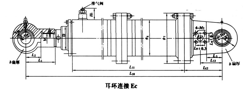
| Model | Bore Diameter D | Rod Diameter d1 | Φ6 | Φ7 | L1 | L2,L3 | L10 | L11 | L12 | L13 | b | R | L9 | d2 | H1 | M | M2 |
|---|---|---|---|---|---|---|---|---|---|---|---|---|---|---|---|---|---|
| CZE100 | 100 | 50 | 146 | 210 | 125 | 70 | 3520 | 3128 | 180 | 102.5 | 60 | 40 | 20 | 46 | M42×2 | M10 | |
| CZE125 | 125 | 50 | 180 | 260 | 135 | 70 | 4315 | 3898 | 185 | 102.5 | 60 | 40 | 20 | 46 | M52×2 | M10 | |
| CZE160 | 160 | 60 | 219 | 310 | 165 | 80 | 4490 | 3991 | 215 | 122.5 | 70 | 56 | 25 | 46 | M68×2 | M12 | |
| CZE200 | 200 | 80 | 280 | 390 | 200 | 100 | 5520 | 4956 | 240 | 142.5 | 90 | 56 | 32 | 46 | M85×2 | M12 | |
| CZE220 | 220 | 90 | 299 | 410 | 225 | 110 | 6770 | - | - | 167.5 | 100 | 73 | 40 | 46 | M90×2 | M16 | |
| CZE250 | 250 | 100 | 330 | 440 | 230 | 120 | 6868 | 6201 | 295 | 177.5 | 110 | 73 | 40 | 46 | M100×2 | M16 | |
| CZE280 | 280 | 110 | 370 | 500 | 250 | 135 | 8201 | - | - | 187.5 | 125 | 73 | 50 | 46 | M110×2 | M16 | |
| CZE320 | 320 | 125 | 420 | 540 | 265 | 145 | 8321 | 7577 | 330 | 202.5 | 135 | 73 | 50 | 46 | M130×2 | M16 | |
| CZE360 | 360 | 140 | 465 | 625 | 370 | 210 | 9882 | - | - | 300 | 160 | 103 | 65 | 46 | M140×2 | M22 | |
| CZE400 | 400 | 150 | 530 | 690 | 400 | 210 | 10187 | - | - | 320 | 200 | 103 | 20 | 46 | M160×2 | M22 | |
| CZG100 | 100 | 50 | 152 | 240 | 135 | 70 | 2530 | 2128 | 180 | 102.5 | 60 | 40 | 20 | 46 | M52×2 | M10 | |
| CZG125 | 125 | 60 | 200 | 310 | 165 | 80 | 3070 | 2618 | 195 | 112.5 | 70 | 40 | 20 | 46 | M68×2 | M10 | |
| CZG160 | 160 | 80 | 250 | 370 | 200 | 100 | 3860 | 3310 | 240 | 142.5 | 90 | 56 | 25 | 46 | M85×3 | M12 | |
| CZG200 | 200 | 100 | 305 | 430 | 230 | 120 | 4685 | 4070 | 270 | 162.5 | 110 | 56 | 32 | 46 | M100×3 | M12 | |
| CZG250 | 250 | 125 | 350 | 500 | 265 | 145 | 5815 | 5090 | 335 | 202.5 | 135 | 73 | 40 | 46 | M130×3 | M16 | |
| CZG320 | 320 | 160 | 450 | 630 | 330 | 200,180 | 7075 | 6235 | 380 | 237.5 | 170 | 73 | 50 | 46 | M160×3 | M16 | |
Installation and Connection Dimensions for CZE Series Single-Acting Plunger-Type Marine Hydraulic Cylinders (Type N: Internal Ball-Joint Connection)
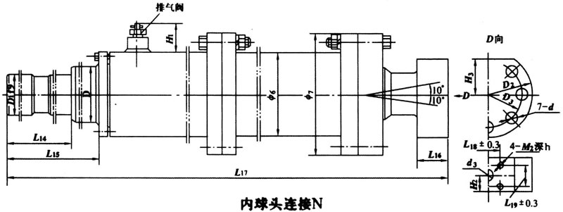
| Model | Bore D | D1 | D2 | D3 | L14 | L15 | L16 | L17 | L18 | L19 | d3 | d4 | H2 | H3 | h | M2 |
|---|---|---|---|---|---|---|---|---|---|---|---|---|---|---|---|---|
| CZE100 | 100 | 75 | 160 | 125 | 150 | 214 | 65 | 3510 | 52 | 28 | 32 | 18 | 35 | 65 | 16 | M10 |
| CZE125 | 160 | 120 | 250 | 205 | 200 | 234 | 105 | 4500 | 80 | 45 | 50 | 22 | 55 | 108 | 18 | M12 |
| CZE160 | 250 | 210 | 350 | 300 | 250 | 249 | 145 | 5795 | 120 | 70 | 80 | 26 | 75 | 158 | 24 | M16 |