Tower crane
Hydraulic jacking system
Drawing on the strengths of multiple enterprises, we have developed a high-performance hydraulic jacking system suitable for tower cranes ranging from 20 to 1,200 tonne-meters. It features a rational design, compact structure, stable performance, and reliable safety.


Product Overview
The TQY series hydraulic jacking system for self-erecting tower cranes is a product developed by our company by integrating the strengths of multiple enterprises; it serves as the hydraulic drive and control system for raising or dismantling the tower crane mast (i.e., adding or removing mast sections).
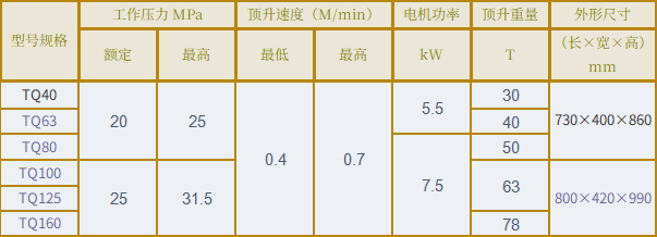
This system features a rational design, compact structure, stable performance, and high safety and reliability; it is suitable for tower cranes ranging from 20 to 1,200 tonne-meters and can also serve as a hydraulic drive system for other standalone actuators.
- The oil tank is welded from 3mm-thick high-quality steel plate, featuring a compact, rational structure and a modern, aesthetically pleasing design.
- Equipped with a protective cover to prevent water and dust from entering the tank, making it suitable for outdoor operating environments.
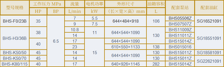
- Utilizes a high-pressure gear pump with a rated working pressure of 20 MPa, featuring an integrated manifold design.
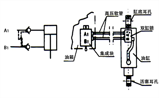
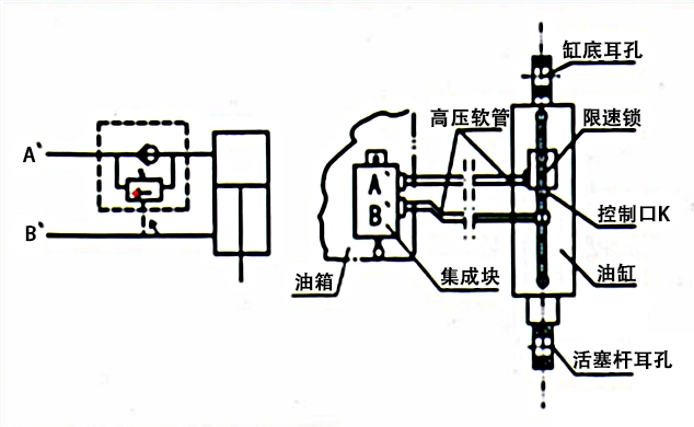
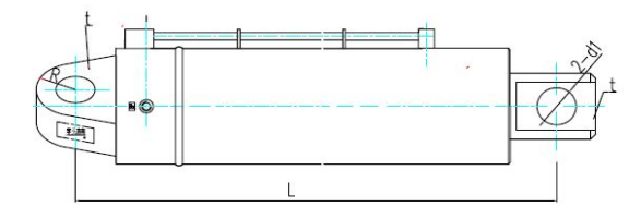
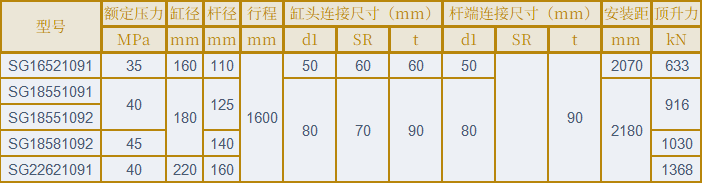
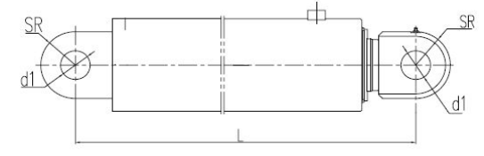
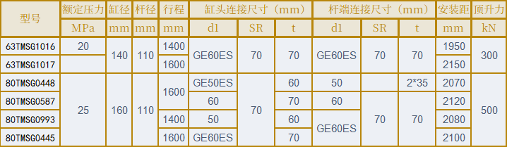
- The actuating assembly consists of a bidirectional hydraulic lock (or speed-limiting lock) and a lifting cylinder.
- Employs a vertical motor configuration to effectively prevent pump cavitation.
Working Principle
- An electric motor drives a hydraulic pump to convert electrical energy into hydraulic energy; control valves then direct the flow to the hydraulic cylinder, converting the energy into mechanical force to drive the load and separate the tower cap from the main tower body (allowing for the addition or removal of mast sections), thereby completing an operating cycle.
- The system utilizes a bidirectional return-flow throttling speed control mechanism to effectively regulate the jacking and retracting speeds of the tower cap. Hydraulic locks or speed-limiting locks are installed in the hydraulic circuit, ensuring the cylinder can hold its position at any point during operation and preventing hazardous uncontrolled descent of the tower cap in the event of a sudden power failure or circuit breaker trip.
- The relief valve, bidirectional throttle check valves, and manual directional control valve (M-spool configuration) are all mounted on an integrated manifold block; this design minimizes pipeline losses and results in a more compact, aesthetically pleasing structure.