HSG*01 Series
Industrial Hydraulic Cylinders
The HSG※01-E series double-acting, single-rod piston hydraulic cylinder serves as an actuator for reciprocating linear motion within hydraulic systems. It features a simple structure, reliable operation, ease of installation and disassembly, and straightforward maintenance, while offering versatile mounting options and selectable cushioning configurations.
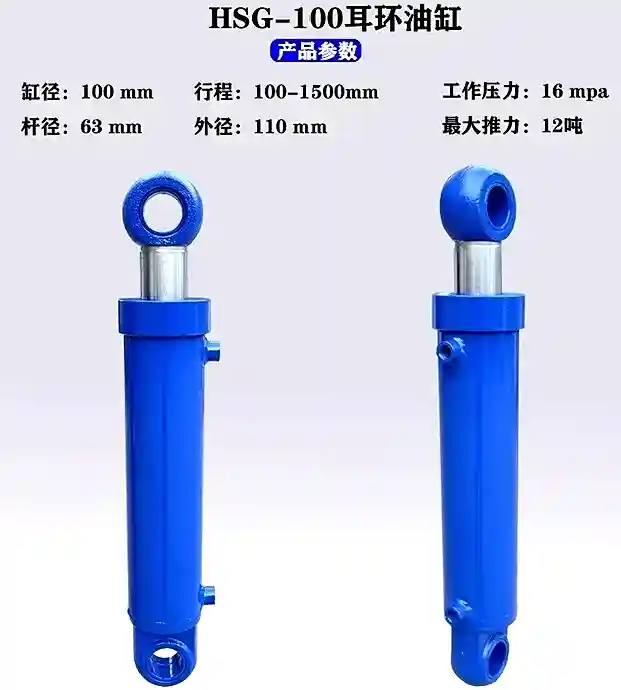
Applications and Features
The HSG※01-E series comprises double-acting, single-rod piston hydraulic cylinders designed to provide reciprocating linear motion within hydraulic systems.
- Simple structure, reliable performance: Proven design of core components ensures stable, long-term operation.
- Convenient installation and easy maintenance: Modular design facilitates on-site installation and servicing.
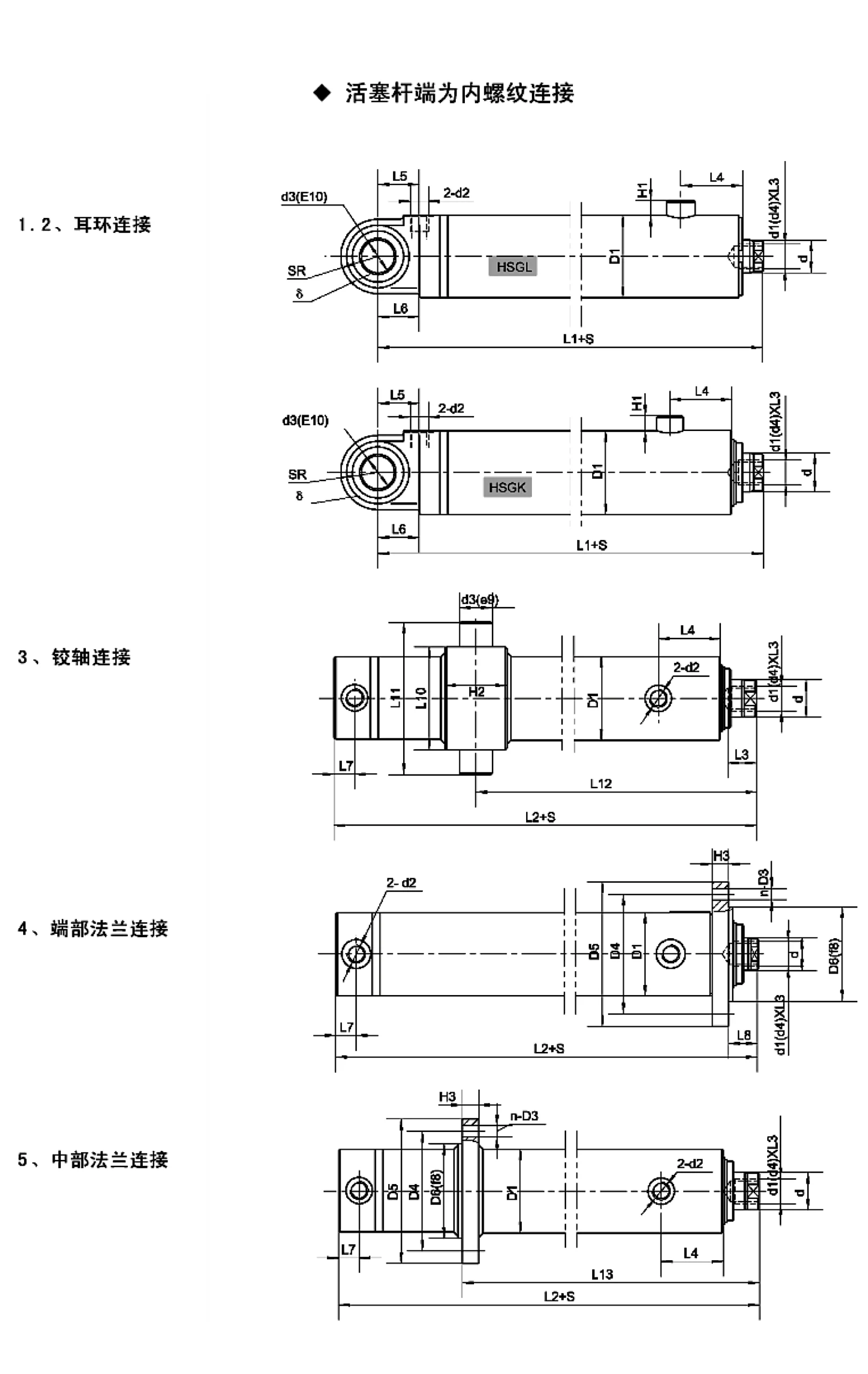
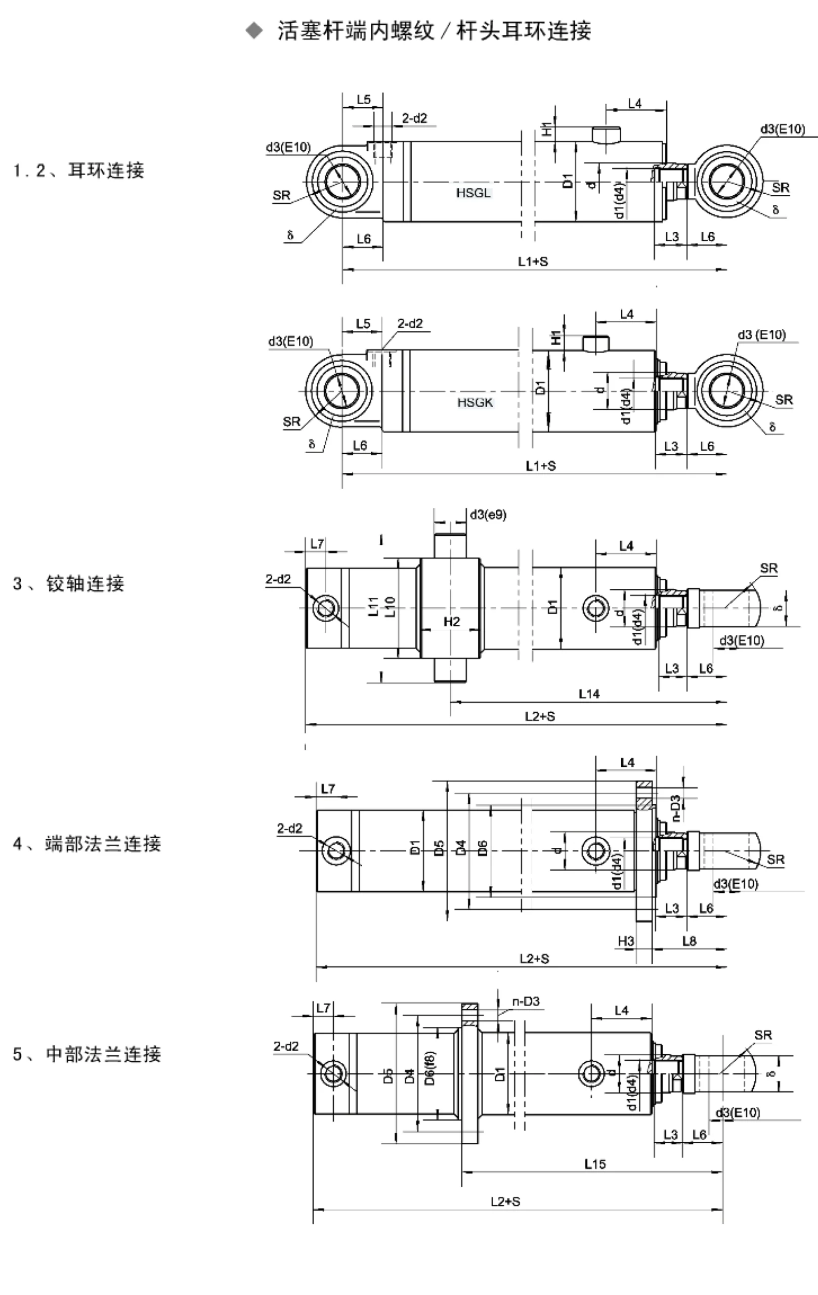
- Versatile connection options: Offers various mounting configurations, including clevis, trunnion, and flange connections.
- Flexible cushioning options: Cushioning can be selected based on requirements—at both ends, at the cap end, at the rod end, or with no cushioning.
Applications: Construction machinery, mining equipment, hoisting and transport machinery, metallurgical equipment, and other machinery industries.
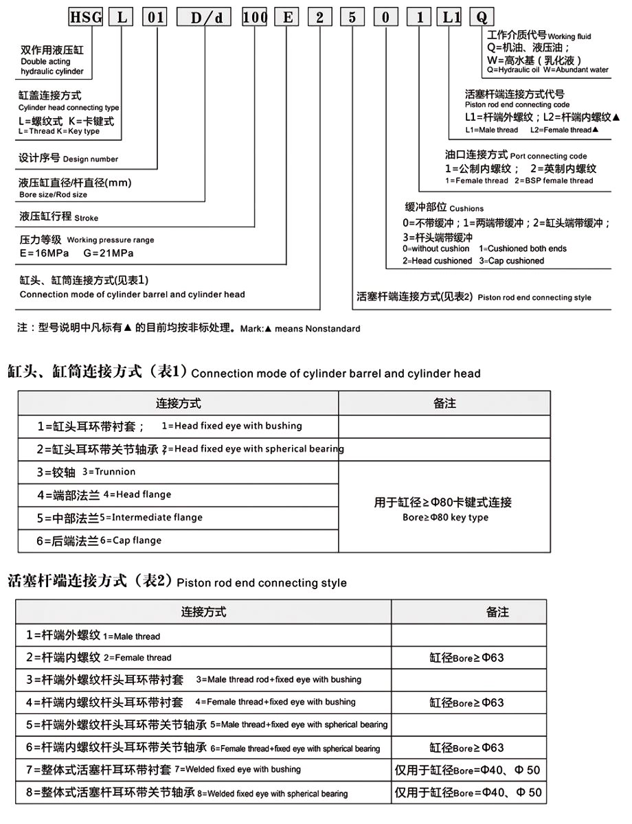
Selection Guide
- Step 1: Refer to the “Model Designation” to determine the codes for the connection type and cushioning configuration based on specific requirements.
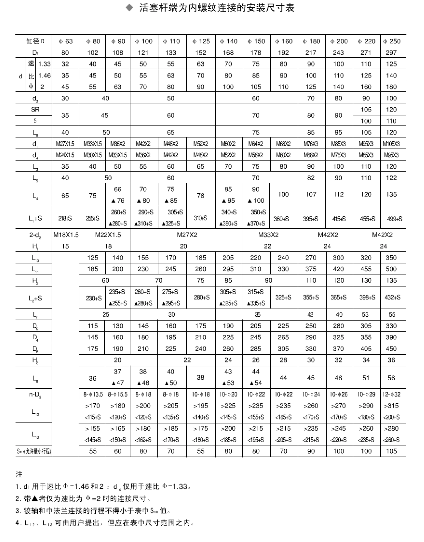
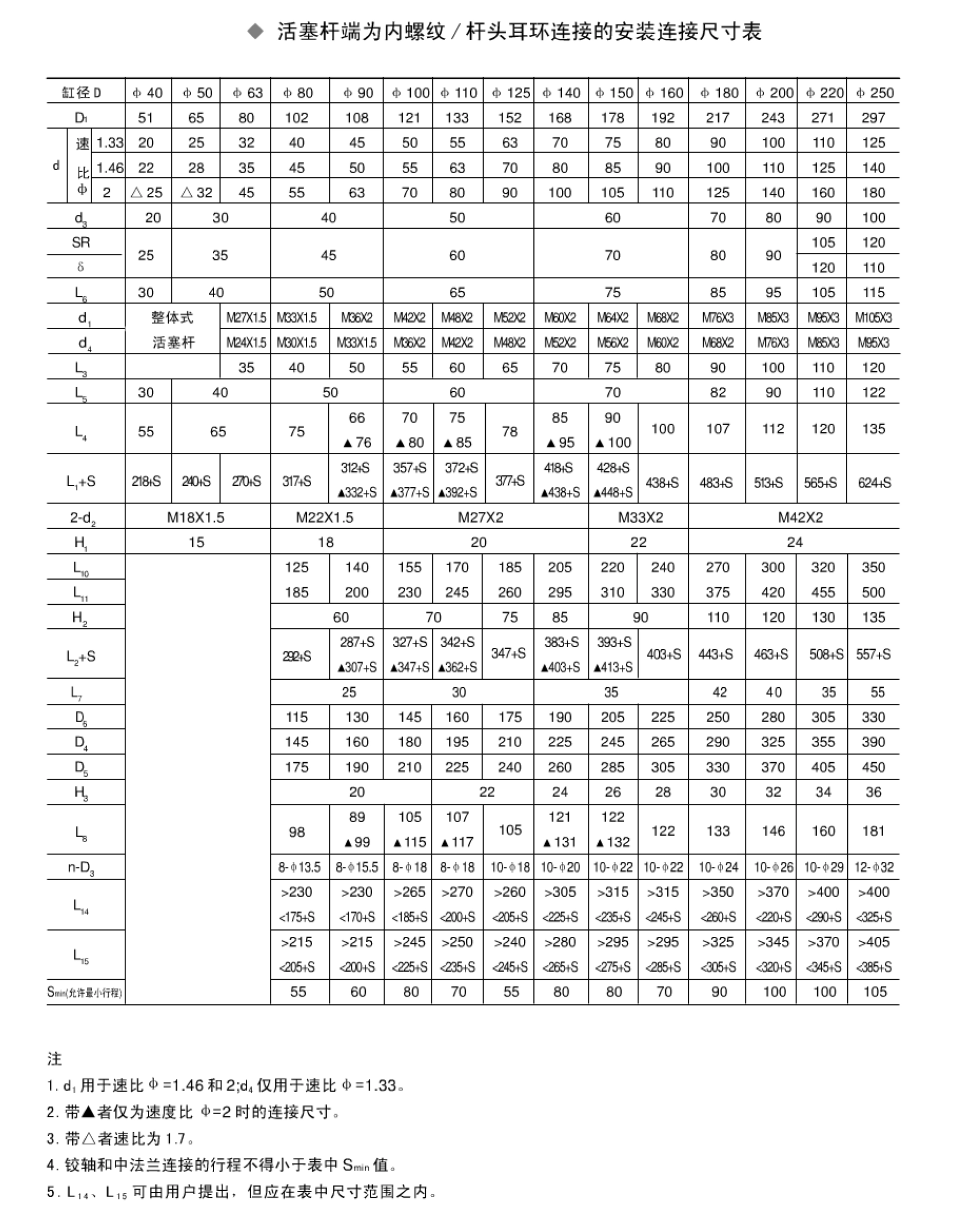
- Step 2: Determine the external mounting and connection dimensions based on the structural type, bore size, speed ratio, etc.
- Step 3: Specify the complete model number, stroke, and mounting distance when placing an order. The format is as follows:
Note: If the required mounting distance matches the value in the dimension table, it need not be specified in the order; however, if it differs, it must be specified. The required mounting distance must fall within the range specified in the dimension table.
Example: For a hydraulic cylinder with a key-lock cylinder head, a middle-flange cylinder barrel connection, no cushioning, and an internal thread at the rod end; with a bore of φ80mm, rod diameter of φ40mm, stroke S=1000mm, and mounting distance L13=500mm, the order model is: HSGK01-80/40E-52101000×500
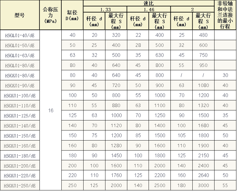
1. The speed ratio Φ refers to the ratio of the piston’s effective area to the effective area of the rod-side chamber.
2. For the speed ratio of 1.46, the rod diameter belongs to the preferred series.
3. Maximum stroke guidelines: Φ=1.33, S=8D; Φ=1.46, S=10D; Φ=2, S=12D.
4. If the required stroke S exceeds the maximum stroke specified in the table, the matter should be resolved through mutual consultation.
5. The minimum stroke for mountings other than trunnion or intermediate flange types is as specified in the table above.
6. 1 MPa is approximately equal to 10 kgf/cm².
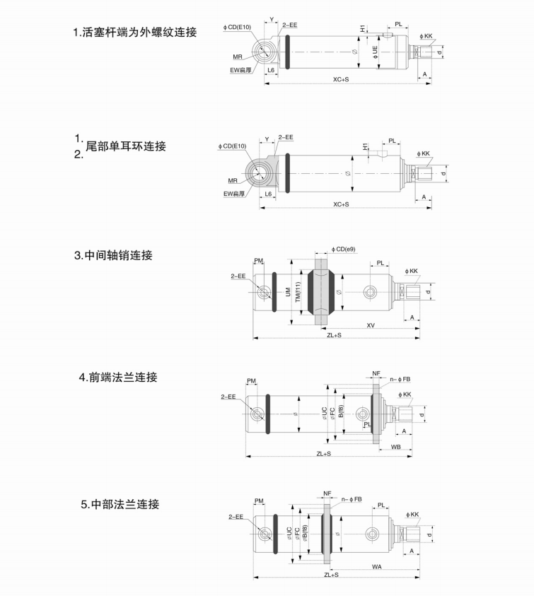
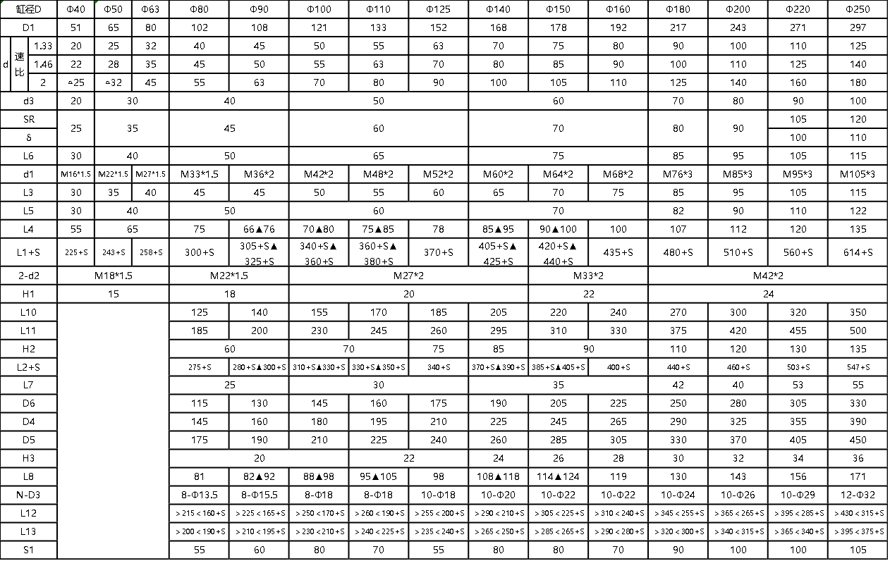 Note
1. Items marked with ▲ indicate connection dimensions applicable only when the speed ratio Φ is 2.
2. Items marked with △ indicate a speed ratio of 1.7.
3. The stroke for the connection between the pivot pin and the intermediate flange must not be less than the Smin value listed in the table.
4. Dimensions L₁₂ and L₁₃ may be specified by the user, provided they fall within the ranges listed in the table.
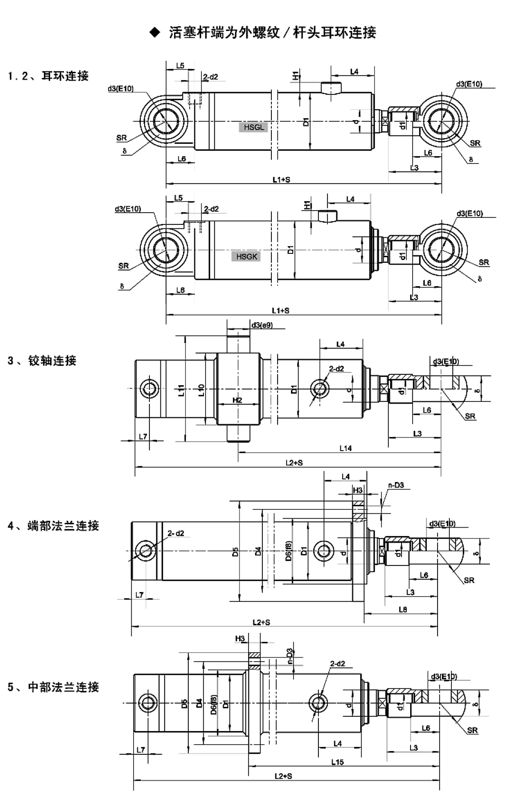
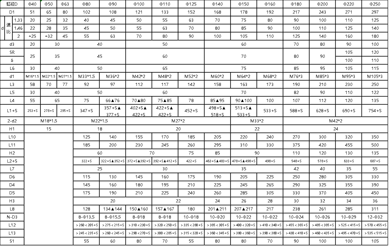 Note
1. Items marked with ▲ indicate connection dimensions applicable only when the speed ratio Φ is 2.
2. Items marked with △ indicate a speed ratio of 1.7.
3. The stroke for the connection between the pivot pin and the intermediate flange must not be less than the Smin value listed in the table.
4. Dimensions L₁₂ and L₁₃ may be specified by the user, provided they fall within the ranges listed in the table.